Hello Readers:
I have started this blog to show you Embedded C programming for 8051 family microcontroller using KEIL compiler. The KISS philosophy is used to write this tutorial. What is KISS? Keep It Simple, Stupid!
2. Manipulating Port Pins
This section teaches you how to manipulate port pins bytewise and bitwise.
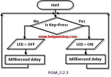
2.2 Bitwise [single bit]
Now we see how to control port pins bitwise.
This program is same as PGM_226.C, only change is here instead of KEY we are using IRDetector module which is readily available in market. Hence this program acts as a mini project and alarms the user when any intruder is detected in its vicinity.

Code explanation:
Line 08 & 07: Declaring 0th & 1st bit of Port 2 as Buzzer & IRDectector bits respectively.
Line 16: This statement makes IRDetector pin as input pin.
Line 17: This statement creates infinite loop.
Line 18: The if control structure checks whether IRDetector pin is HIGH, and if yes i.e., intruder is detected then calls Buzzer() function. Note that when intruder is detected the IR Detector module sends HIGH signal to pin.
Line 21: This Buzzer() function generates intermittent sound when KEY is pressed.
Note: you can change the MSDelay() parameters from 25 to anything and hear different tones at buzzer output.

After typing the code, press F7 or click Project->Build Target for building the source code. If there are no typical errors file will build successively and shows zero errors and zero warnings.
Now enter into debug mode by pressing Ctrl+F5 or click Debug->Start/Stop Debug Session menu. To get Port 2 tab click Peripherals->I/O Ports->Port 2 menu.
Run the program by pressing F5 or clicking Debug->Run. Since this needs IRDetector’s intruder signal for simulation, you cannot simulate it fully. You can add this program file to PGM_224 project file, which is available in 2.2.4 section [or click here]. Copy the PGM_224 project folder and paste it once again and rename it as PGM_227. Now open PGM_227 project in KEIL V4.0 and remove the source file PGM_224.C and add this PGM_227.C file to it. Now compile the project and run the program in debug mode. For program verification steps please refer 2.2.4 section as they are same with slight change [instead of LED here you are driving Buzzer].
If you generate HEX file of this program, burn it into your target chip’s memory using suitable uploader and connecting IRDetector and Buzzer to Port 2 pins you can hear intermittent buzzer sound when intruder is detected. To stop running the program press red ‘x’ mark icon or click Debug->Stop. To get back the compile mode press Ctrl+F5 or click Debug->Start/Stop Debug Session menu.
...till next post bye-bye & take care.