Thursday, January 20, 2011

4.1 Interfacing 4x4 key pad

Hello Readers:

I have started this blog to show you Embedded C programming for 8051 family microcontroller using KEIL compiler. The KISS philosophy is used to write this tutorial. What is KISS? Keep It Simple, Stupid!


4. Key Pad Interface [4x4]

This section teaches you how to interface 4x4 matrix key pad to microcontroller chip.

4.1 Interfacing 4x4 key pad


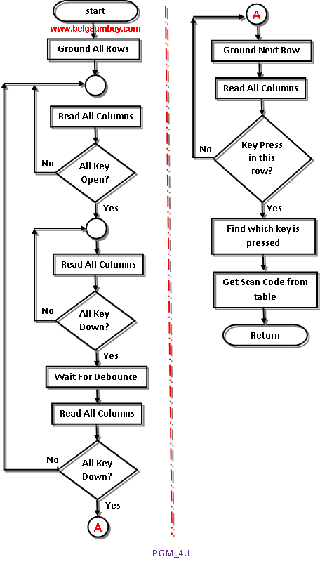
The key pad interface is widely demanded hardware interface unit in embedded systems. This program is better understood with closer look of code lines and flow chart diagram.

Start KEIL V4.01 and close projects, if any are open. Now start new project with Device -> Generic->8051 [all variants] for general 8051 family target chip. Add a new text file, name it Pgm_41.C and add it to above created project as a source file. It is time to add code to Pgm_41.C, so type below shown code in it.


Code explanation: The program goes thorough the following four major stages:
1.    To make sure that the preceding key has been released, 0s are output to all rows at once, and the columns are read and checked repeatedly unitl all the columns are high. When all columns are found to be high, the program waits for a short amount of time before it goes to the next stage of waiting for a key to be pressed.
2.    To see if any key is pressed, the columns are scanned over and over in an infinite loop unitl one of them has a 0 on it. Remember that the output latches connected to rows still have their initial zeros (provided in stage 1), making thm grounded. After the key press detection, the microcontroller waits 20ms for the bounce and then scans the columns again. This serves two functions: (a) it ensures that the first key press detection was not an erroneous one due to a spike noise, and (b) the 20-ms delay prevents the same key press from being interpreted as a multiple key press. If after the 20-ms delay the key is still pressed, it goes to the next stage to detect which row it belongs to; otherwise, it goes back into the loop to detect a real key press.
3.    To detect which row the key press belongs to, the microcontroller grounds one row at a time, reading the columns each time. If it finds that all columns are high, this means that the key press cannot belong to that row; therefore, it grounds the next row and continues until it finds the row the key press belongs to. Upon finding the row that the key press belongs to, it sets up the starting address for the look-up table holding the scan codes (or the ASCII value) for that row and goes to the next stage to identify the key.
4.    To identify the key press, the microcontroller rotates the column bits, one bit at a time, into the carry flag and checks to see if it is low. Upon finding the zero, it pulls out the ASCII code for that key from the look-up table; otherwise, it increments the pointer to point to the next element of the look-up table.

While the key press detection is standard for all keyboards, the process for determining which key is pressed varies. The look-up table method can be modified to work with any matrix up to 8 x 8.

Below is the flow chart diagram of program PGM_41.C.


After typing the code, press F7 or click Project->Build Target for building the source code. If there are no typical errors file will build successively and shows zero errors and zero warnings. You can burn the hex file generated by this program for hardware simulation. Note that this program needs user input i.e., KEY press for software simulation. Note that Port 1 is used as output port or row port and Port 2 is used as input port or column port.

<End of 4.1 Interfacing 4x4 key pad>
 
...till next post bye-bye & take care.

Sunday, January 16, 2011

3.2 Sending Characters [2-line-using pointer]

Hello Readers:

I have started this blog to show you Embedded C programming for 8051 family microcontroller using KEIL compiler. The KISS philosophy is used to write this tutorial. What is KISS? Keep It Simple, Stupid!


3. LCD Interface

This section teaches you how to control LCD connected to output port of a microcontroller chip.

3.2 Sending Characters [2-line-using pointer]


This program displays “Hi!” on LCD screen continuously. Here LCD is configured for two lines and both lines are used for displaying message. Note that R/W [Read/Write] pin is connected permanently to ground [in hardware] as always write operation is used in this program. When key press detected it shows different message and when no key press [default] program shows welcome               message. The pointers are used to store string messages and retrieved using while loop structure.

Start KEIL V4.01 and close projects, if any are open. Now start new project with Device -> Generic->8051 [all variants] for general 8051 family target chip. Add a new text file, name it Pgm_32.C and add it to above created project as a source file. It is time to add code to Pgm_32.C, so type below shown code in it.

Code explanation:
Line 09 to 12: The string messages are assigned to pointer variables.
Line 21: The Switch pin is made input pin.
Line 22: The LCD is initialized.
Line 23: This statement says run this program infinite times.
Line 25: The if control structure checks whether switch is pressed, if yes executes its code block.
Line 28: This statement assigns “WELCOME 2 SYSTEM” string to transmitter pointer.
Line 29: This lcd_data() function sends above string to LCD.
Line 31: This command forces cursor to beginning of second line of LCD.
Line 32: This statement assigns “PRESS ANY KEY” string to transmitter pointer.
Line 33: This lcd_data() function sends above string to LCD.
Line 38: This statement assigns “KEYPRESS DETECTED” string to transmitter pointer.
Line 39: This lcd_data() function sends above string to LCD.
Line 41: This command forces cursor to beginning of second line of LCD.
Line 42: This statement assigns “2nd LINE MSG” string to transmitter pointer.
Line 43: This lcd_data() function sends above string to LCD.
Line 53: This lcd_init() function initializes the LCD.
Line 35: This lcd_cmd() function sends parameter commands to LCD.
Line 46: This lcd_data() function sends parameter data to LCD.
Line 57: This delay() function supplies delay between each command execution.

Below is the flow chart diagram of program PGM_32.C.

After typing the code, press F7 or click Project->Build Target for building the source code. If there are no typical errors file will build successively and shows zero errors and zero warnings. You can burn the hex file generated by this program for hardware simulation and for software simulation we need below program.

Note that this program needs user input i.e., KEY press for software simulation. So download already compiled and crated project folder by clicking here. Open the downloaded project in KEIL V4.0 and enter into debug mode. When you enter into debug mode your debug windows looks like below screen shot.


To enter into debug mode press Ctrl+F5 or click Debug->Start/Stop Debug Session menu. The LCD is connected to Port 1. So we want to watch the Port 1 pins along with Port 2 & Port 3, while running this program for changing values. To get Port 1 tab click Peripherals->I/O Ports->Port 1 menu and repeat this for Port 2 & Port 3 also. Here we need ToolBox for inputting key press signals, and you get it by clicking View->Toll Box Window menu. Now your debug windows looks like above screen shot.

Run the program by pressing F5 or clicking Debug->Run. You can see initially LCD port bit are showing welcome message in binary form. Now press Set SWITCH button on ToolBox. Port 1 bits shows second set of messages. To turn off these messages press Clr SWITCH button from ToolBox. Thus we verified that our program will work fine with hardware interface. To stop running the program press red ‘x’ mark icon or click Debug->Stop.

To get back the compile mode press Ctrl+F5 or click Debug->Start/Stop Debug Session menu.   

<End of 3.2   Sending Characters [2-line-using pointer]>


...till next post bye-bye & take care.