Friday, March 4, 2011

7.4 Tx & Rx characters simultaneously

Hello Readers:

I have started this blog to show you Embedded C programming for 8051 family microcontroller using KEIL compiler. The KISS philosophy is used to write this tutorial. What is KISS? Keep It Simple, Stupid!

7. Serial Port Interface

This section teaches you how to send data and receive data from personal computer through serial port.

7.4 Tx & Rx characters simultaneously

The program receives as-well as transmits serial data through serial port. When key is pressed data will be sent and otherwise data will be received. The transmitting data will be in R-range-direction [R20 R21 R22 …] format and can be seen on UART#1 window. This is because usually embedded system sends data in certain format so that receiver unit can distinguish it from other data it may receive on same port. 

Start KEIL V4.01 and close projects, if any are open. Now start new project with Device -> Generic->8051 [all variants] for general 8051 family target chip. Add a new text file, name it Pgm_74.C and add it to above created project as a source file. It is time to add code to Pgm_74.C, so type below shown code in it.


Code explanation: This program is nothing but previous transmitter & receiver programs mixture. No flow chart is provided as it makes more confusing.

After typing the code, press F7 or click Project->Build Target for building the source code. If there are no typical errors file will build successively and shows zero errors and zero warnings.
Now enter into debug mode by pressing Ctrl+F5 or click Debug->Start/Stop Debug Session menu. Our program is sending character in ‘Rrd’ format [R20 R21 R22 …] to UART #1 continuously. So we want to watch the UART #1 while running this program for receiving values. To get UART #1 tab click View->Serial Windows->UART #1 text.

Run the program by pressing F5 or clicking Debug->Run. You can see the Character ‘R20 R21 …’ on UART #1 tab continuously. The receiving character simulation is not possible as such facility is not provided in this program.

If you generate HEX file of this program, burn it into your target chip’s memory using suitable uploader and connecting chip to PC with the help of serial cable you can watch sending/receiving characters on PC’s Hyper Terminal & on chips LCD module simultaneously. To stop running the program press red ‘x’ mark icon or click Debug->Stop.

To get back the compile mode press Ctrl+F5 or click Debug->Start/Stop Debug Session menu.  

<End of 7.4   Tx & Rx characters simultaneously >


...till next post bye-bye & take care.

Monday, February 28, 2011

7.3 Receiving characters

Hello Readers:

I have started this blog to show you Embedded C programming for 8051 family microcontroller using KEIL compiler. The KISS philosophy is used to write this tutorial. What is KISS? Keep It Simple, Stupid!

7. Serial Port Interface

This section teaches you how to send data and receive data from personal computer through serial port.

7.3 Receiving characters

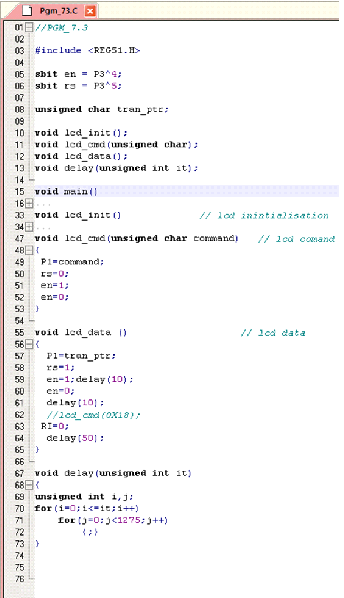
This program is used to receive the characters sent by PC or other device through serial cable. Since LCD is used to display the received characters, LCD modules are inserted in this program. 

Start KEIL V4.01 and close projects, if any are open. Now start new project with Device -> Generic->8051 [all variants] for general 8051 family target chip. Add a new text file, name it Pgm_73.C and add it to above created project as a source file. It is time to add code to Pgm_73.C, so type below shown code in it.


Code explanation: This program is better understood by referring flow chart diagram closely.
Below is the flow chart diagram of program PGM_73.C.

 
After typing the code, press F7 or click Project->Build Target for building the source code. If there are no typical errors file will build successively and shows zero errors and zero warnings. No need to enter into debug mode as serial data receiving provision is not provided in this program.

If you generate HEX file of this program, burn it into your target chip’s memory using suitable uploader and connecting chip to PC with the help of serial cable you can watch received character sent by PC’s Hyper Terminal to chip on LCD. To stop running the program press red ‘x’ mark icon or click Debug->Stop.

To get back the compile mode press Ctrl+F5 or click Debug->Start/Stop Debug Session menu.   

<End of 7.3   Receiving characters >
 
...till next post bye-bye & take care.

Thursday, February 24, 2011

7.2 Sending Three Characters

Hello Readers:

I have started this blog to show you Embedded C programming for 8051 family microcontroller using KEIL compiler. The KISS philosophy is used to write this tutorial. What is KISS? Keep It Simple, Stupid!

7. Serial Port Interface

This section teaches you how to send data and receive data from personal computer through serial port.

7.2 Sending Three Characters


This program sends three letters to PC through serial port. One can see this repeatedly sending character on Terminal program. To get Terminal Program in Windows click as follows:

Start Menu->All Programs -> Accessories -> Communications  -> HyperTerminal 

Start KEIL V4.01 and close projects, if any are open. Now start new project with Device -> Generic->8051 [all variants] for general 8051 family target chip. Add a new text file, name it Pgm_72.C and add it to above created project as a source file. It is time to add code to Pgm_72.C, so type below shown code in it.


Code explanation: This program is similar to previous program, PGM_71.C only extended to send three characters. Note that carriage [0x0D] and Line Feed [0x0A] are added after each ‘YES’. This makes it more readable and same is observed in UART#1 window while simulating it. No flow chart diagram is provided as it makes unnecessarily confusing. 


After typing the code, press F7 or click Project->Build Target for building the source code. If there are no typical errors file will build successively and shows zero errors and zero warnings.
Now enter into debug mode by pressing Ctrl+F5 or click Debug->Start/Stop Debug Session menu. Our program is sending characters ‘Y’, ‘E’, ‘S’ with carriage and line feed to UART #1 continuously. So we want to watch the UART #1 while running this program for receiving values. To get UART #1 tab click View->Serial Windows->UART #1 text.

Run the program by pressing F5 or clicking Debug->Run. You can see the Characters are arranged as ‘YES’ and printed each time on new line on UART #1 tab continuously. If you generate HEX file of this program, burn it into your target chip’s memory using suitable uploader and connecting chip to PC with the help of serial cable you can watch character ‘YES’ on PC’s Hyper Terminal. To stop running the program press red ‘x’ mark icon or click Debug->Stop.

To get back the compile mode press Ctrl+F5 or click Debug->Start/Stop Debug Session menu.   

<End of 7.2   Sending Three Characters >
 
...till next post bye-bye & take care.

Sunday, February 20, 2011

7.1 Sending Single Characters

Hello Readers:

I have started this blog to show you Embedded C programming for 8051 family microcontroller using KEIL compiler. The KISS philosophy is used to write this tutorial. What is KISS? Keep It Simple, Stupid!

7. Serial Port Interface

This section teaches you how to send data and receive data from personal computer through serial port.

7.1 Sending Single Characters  


This program sends letter ‘R’ to PC through serial port. One can see this repeatedly sending character on Terminal program. To get Terminal Program in Windows click as follows:

Start Menu->All Programs -> Accessories -> Communications  -> HyperTerminal
Start KEIL V4.01 and close projects, if any are open. Now start new project with Device -> Generic->8051 [all variants] for general 8051 family target chip. Add a new text file, name it Pgm_71.C and add it to above created project as a source file. It is time to add code to Pgm_71.C, so type below shown code in it.
 
Code explanation: Please refer flow chart diagram for what each code line does.
Below is the flow chart diagram of program PGM_71.C.
  
After typing the code, press F7 or click Project->Build Target for building the source code. If there are no typical errors file will build successively and shows zero errors and zero warnings.
Now enter into debug mode by pressing Ctrl+F5 or click Debug->Start/Stop Debug Session menu. Our program is sending character ‘R’ to UART #1 continuously. So we want to watch the UART #1 while running this program for receiving values. To get UART #1 tab click View->Serial Windows->UART #1 text.

Run the program by pressing F5 or clicking Debug->Run. You can see the Character ‘R’ on UART #1 tab continuously. If you generate HEX file of this program, burn it into your target chip’s memory using suitable uploader and connecting chip to PC with the help of serial cable you can watch character ‘R’ on PC’s Hyper Terminal. To stop running the program press red ‘x’ mark icon or click Debug->Stop.

To get back the compile mode press Ctrl+F5 or click Debug->Start/Stop Debug Session menu.   
<End of 7.1   Sending Single Characters >

...till next post bye-bye & take care.

Wednesday, February 16, 2011

6.2 Counter 1 Mode 2 test

Hello Readers:

I have started this blog to show you Embedded C programming for 8051 family microcontroller using KEIL compiler. The KISS philosophy is used to write this tutorial. What is KISS? Keep It Simple, Stupid!

6. Counters

This section teaches you how to configure timers as counters.

6.2  Counter 1 Mode 2 test 


This program is used to count the visitors and total count range is 8 bits as Counter 1 is in Mode 2 auto reload. You can feed 1 Hz external clock into pin T1 (P3.5).

Start KEIL V4.01 and close projects, if any are open. Now start new project with Device -> Generic->8051 [all variants] for general 8051 family target chip. Add a new text file, name it Pgm_62.C and add it to above created project as a source file. It is time to add code to Pgm_62.C, so type below shown code in it.
 
Code explanation:
Line 11: make T1 an input.
Line 12: set TimerMODe register for Counter 1 in mode 2.
Line 13: Initialize register to zero.
Line 17: Start the timer1.
Line 18: Place value on LED port pins.
Line 19: do the above steps till Timer Flag is not overflowed.
Line 20 & 21: Reset Timer and Timer Flag for next iteration. 

Below is the flow chart diagram of program PGM_62.C.
 
After typing the code, press F7 or click Project->Build Target for building the source code. If there are no typical errors file will build successively and shows zero errors and zero warnings. You cannot simulate this as external clock pulse is not supplied in this program.

If you generate HEX file of this program, burn it into your target chip’s memory using suitable uploader and connecting 1 Hz external clock to Port 2 you can watch LEDs incrementing in binary form. To stop running the program press red ‘x’ mark icon or click Debug->Stop.

To get back the compile mode press Ctrl+F5 or click Debug->Start/Stop Debug Session menu.  
<End of 6.2   Counter 1 Mode 2 test >
 
...till next post bye-bye & take care.
Saturday, February 12, 2011

6.1 Counter 0 Mode 1 test

Hello Readers:

I have started this blog to show you Embedded C programming for 8051 family microcontroller using KEIL compiler. The KISS philosophy is used to write this tutorial. What is KISS? Keep It Simple, Stupid!

6. Counters
This section teaches you how to configure timers as counters.
 
6.1 Counter 0 Mode 1 test


This program is used to count the visitors and total count range is 16 bits as Counter 0 is in Mode 1. You can feed 1 Hz external clock into pin T0 (P3.4).

Start KEIL V4.01 and close projects, if any are open. Now start new project with Device -> Generic->8051 [all variants] for general 8051 family target chip. Add a new text file, name it Pgm_61.C and add it to above created project as a source file. It is time to add code to Pgm_61.C, so type below shown code in it.
  
Code explanation:
Line 09: make T0 an input.
Line 10: set TimerMODe register for Counter 0 in mode 1.
Line 11 &12: Initialize both registers to zero.
Line 16: Start the timer0.
Line 17 &18: Place value on LED port pins.
Line 19: do the above steps till Timer Flag is not overflowed.
Line 20 & 21: Reset Timer and Timer Flag for next iteration.

Below is the flow chart diagram of program PGM_61.C.
 
After typing the code, press F7 or click Project->Build Target for building the source code. If there are no typical errors file will build successively and shows zero errors and zero warnings. You cannot simulate this as external clock pulse is not supplied in this program.

If you generate HEX file of this program, burn it into your target chip’s memory using suitable uploader and connecting 1 Hz external clock to Port 2 you can watch LEDs incrementing in binary form. To stop running the program press red ‘x’ mark icon or click Debug->Stop.

To get back the compile mode press Ctrl+F5 or click Debug->Start/Stop Debug Session menu.   
<End of 6.1   Counter 0 Mode 1 test >
 
...till next post bye-bye & take care.

Tuesday, February 8, 2011

5.2.2 Rotating Single DC Motor [25% duty cycle]

Hello Readers:

I have started this blog to show you Embedded C programming for 8051 family microcontroller using KEIL compiler. The KISS philosophy is used to write this tutorial. What is KISS? Keep It Simple, Stupid!

5. Motor Interface

This section teaches you how to write program for stepper motors and dc motors. In this section no flow chart diagrams are provided, so try to figure out the one from source code.
 

5.2 Dc Motor
Now we see how to write program for DC motors.
5.2.2   Rotating Single DC Motor [25% duty cycle]

The DC motor interface application is usually found in moving robotic vehicle systems. This program shows how to rotate two DC motors [useful in vehicle controlling] with 25% duty cycle. In DC motor 25% duty cycle means, ON time is 25% and OFF time is 75%. 

Start KEIL V4.01 and close projects, if any are open. Now start new project with Device -> Generic->8051 [all variants] for general 8051 family target chip. Add a new text file, name it Pgm_211.C and add it to above created project as a source file. It is time to add code to Pgm_211.C, so type below shown code in it.  
 
Code explanation: Motor is switched ON for 25 Milliseconds and OFF for 75  Milliseconds delay continuously.

After typing the code, press F7 or click Project->Build Target for building the source code. If there are no typical errors file will build successively and shows zero errors and zero warnings.
Now enter into debug mode by pressing Ctrl+F5 or click Debug->Start/Stop Debug Session menu. Our program is toggling Port 2’s motor pins continuously. So we want to watch the Port 2 pins while running this program for toggling values. To get Port 2 tab click Peripherals->I/O Ports->Port 2 text.

Run the program by pressing F5 or clicking Debug->Run. You can see the toggling values on Port 2 tab continuously in binary form. If you generate HEX file of this program, burn it into your target chip’s memory using suitable uploader and connecting two DC motors to Port 2 you can watch DC motor rotation continuously. To stop running the program press red ‘x’ mark icon or click Debug->Stop.

To get back the compile mode press Ctrl+F5 or click Debug->Start/Stop Debug Session menu.  
<End of 5.2.2 Rotating Single DC Motor [25% duty cycle]>
 
...till next post bye-bye & take care.

Friday, February 4, 2011

5.2.1 Rotating Single DC Motor [50% duty cycle]

Hello Readers:

I have started this blog to show you Embedded C programming for 8051 family microcontroller using KEIL compiler. The KISS philosophy is used to write this tutorial. What is KISS? Keep It Simple, Stupid!


5. Motor Interface

This section teaches you how to write program for stepper motors and dc motors. In this section no flow chart diagrams are provided, so try to figure out the one from source code.


5.2 Dc Motor
Now we see how to write program for DC motors.
5.2.1 Rotating Single DC Motor [50% duty cycle] 


The DC motor interface application is usually found in moving robotic vehicle systems. This program shows how to rotate a DC motor with 50% duty cycle. In DC motor 50% duty cycle means, ON time and OFF time are equal. 

Start KEIL V4.01 and close projects, if any are open. Now start new project with Device -> Generic->8051 [all variants] for general 8051 family target chip. Add a new text file, name it Pgm_521.C and add it to above created project as a source file. It is time to add code to Pgm_521.C, so type below shown code in it. 
 
Code explanation: Motor is switched ON and OFF with equal time delay.

 
After typing the code, press F7 or click Project->Build Target for building the source code. If there are no typical errors file will build successively and shows zero errors and zero warnings.
Now enter into debug mode by pressing Ctrl+F5 or click Debug->Start/Stop Debug Session menu. Our program is toggling Port 2’s motor pin continuously. So we want to watch the Port 2 pins while running this program for toggling values. To get Port 2 tab click Peripherals->I/O Ports->Port 2 text.

Run the program by pressing F5 or clicking Debug->Run. You can see the toggling values on Port 2 tab continuously in binary form. If you generate HEX file of this program, burn it into your target chip’s memory using suitable uploader and connecting DC motor to Port 2 you can watch DC motor rotation continuously. To stop running the program press red ‘x’ mark icon or click Debug->Stop.

To get back the compile mode press Ctrl+F5 or click Debug->Start/Stop Debug Session menu.   
<End of 5.2.1 Rotating Single DC Motor [50% duty cycle]>
 
...till next post bye-bye & take care.