Hello Readers:
I have started this blog to show you Embedded C programming for 8051 family microcontroller using KEIL compiler. The KISS philosophy is used to write this tutorial. What is KISS? Keep It Simple, Stupid!
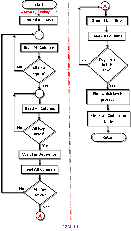
The key pad interface is widely demanded hardware interface unit in embedded systems. This program is better understood with closer look of code lines and flow chart diagram.
Code explanation: The program goes thorough the following four major stages:
1. To make sure that the preceding key has been released, 0s are output to all rows at once, and the columns are read and checked repeatedly unitl all the columns are high. When all columns are found to be high, the program waits for a short amount of time before it goes to the next stage of waiting for a key to be pressed.
2. To see if any key is pressed, the columns are scanned over and over in an infinite loop unitl one of them has a 0 on it. Remember that the output latches connected to rows still have their initial zeros (provided in stage 1), making thm grounded. After the key press detection, the microcontroller waits 20ms for the bounce and then scans the columns again. This serves two functions: (a) it ensures that the first key press detection was not an erroneous one due to a spike noise, and (b) the 20-ms delay prevents the same key press from being interpreted as a multiple key press. If after the 20-ms delay the key is still pressed, it goes to the next stage to detect which row it belongs to; otherwise, it goes back into the loop to detect a real key press.
3. To detect which row the key press belongs to, the microcontroller grounds one row at a time, reading the columns each time. If it finds that all columns are high, this means that the key press cannot belong to that row; therefore, it grounds the next row and continues until it finds the row the key press belongs to. Upon finding the row that the key press belongs to, it sets up the starting address for the look-up table holding the scan codes (or the ASCII value) for that row and goes to the next stage to identify the key.
4. To identify the key press, the microcontroller rotates the column bits, one bit at a time, into the carry flag and checks to see if it is low. Upon finding the zero, it pulls out the ASCII code for that key from the look-up table; otherwise, it increments the pointer to point to the next element of the look-up table.
While the key press detection is standard for all keyboards, the process for determining which key is pressed varies. The look-up table method can be modified to work with any matrix up to 8 x 8.
...till next post bye-bye & take care.


No comments:
Post a Comment